In Digital Takeoff, select Preferences from the menu bar to open the System Preferences window, which has the following tabs: Settings, Display, Image Import,Database, Integration and Colors & Tools.
The Settings tab contains the majority of the options you will use with Digital Takeoff.
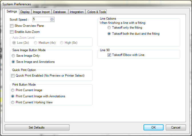
Scroll Speed: This option allows you to set the scroll speed while navigating Sheets and other items.
Show Overview Pane: When checked, Estimating will display thumbnail images. If de-selected, the thumbnail display is hidden. Generally, when the thumbnail image is not displayed, performance for refreshing images and zooming and using the mouse wheel are improved. See Overview Pane.
Enable Auto-Zoom: Activating this option allows the Auto-Zoom feature to be used. Activation of this option enables the Auto-Zoom Level options.
Auto-Zoom Level: This option controls how close to the drawing the Auto-Zoom feature of Digital Takeoff will zoom when in use.
Save Image Button Mode: This option controls the function of the Image Save option on the Main Tool bar.
Save Image Only saves only the changes to the actual drawing (screen rotation, cropping, etc.).
Save Image and Annotations saves both changes to the drawing (screen rotation, cropping, etc.), as well as any annotations on the drawing.
Quick Print Option: This option allows you to bypass the printer selection and preview screens when printing.
Print Button Mode: This option controls the function of the Print option on the Main Tool bar. Select:
Print Current Image
Print Current Image with Annotations
Print Current Working View
Line Options: This option allows you to control whether to takeoff ONLY the fitting or both the duct and the fitting. Select:
Takeoff only the fitting
Takeoff both the duct and the fitting
Line 90:
Select the Line 90Takeoff Elbow with Line check box to have Estimating default to adding elbows when using the Right Angles 90 measuring tool.
To save your settings as your Database defaults, select Set Database Defaults.
To save your changes for the current session, select OK.
The Display tab options give additional customization options for your Digital Takeoff view.
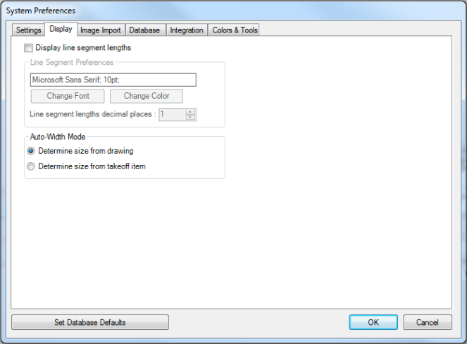
Display line segment lengths: Activating this option causes line segment lengths to be displayed in Digital Takeoff. Activation of this option enables the “Line Segment Preferences” options.
Line Segment Preferences: These options allow you to control how the lengths/values of Lines Segments are formatted:
Use Change Font to select the desired font
Use Change Color to change the color of your default line segments
Line segment lengths decimal places: Enter the desired number of decimal places to be used in Digital Takeoff.
Auto-Width Mode allows you to select:
Determine size from drawing – Estimating examines the drawing to determine the thickness of the line.
Determine
size from takeoff item – The line thickness changes according
the size of the item in Estimating Takeoff.
Note: Lines in Digital
Takeoff have a minimum width, so very small runs of duct will
show as the same thickness; likewise, there may be no perceptible
difference between two runs of duct/pipe that have a small difference
in size (1” vs. 1 and 1/4”)
To save your settings as your Database defaults, select Set Database Defaults.
To save your changes for the current session, select OK.
The Image Import tab contains the options needed for ensuring the quality of your imported Digital Takeoff images.
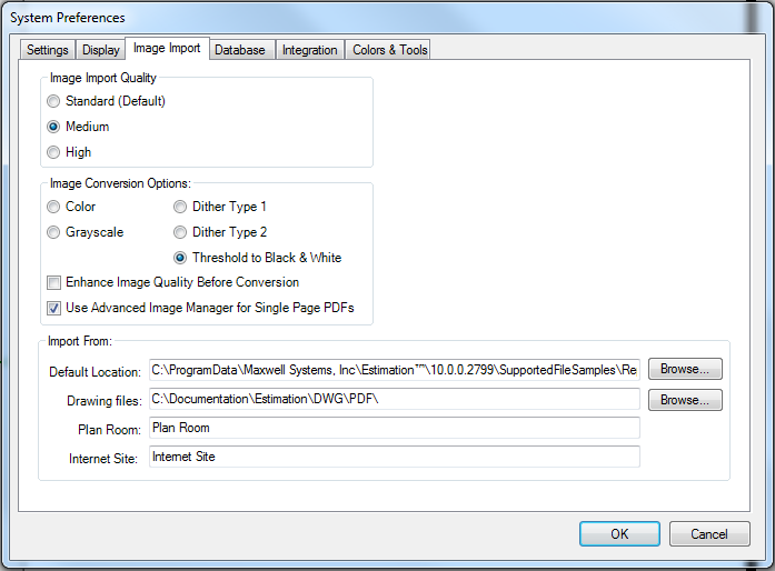
Image Import Quality: This option allows you to select the DPI (dots per inch) resolution for the image. Each dot or pixel on the Image Display represents approximately 1/100 of an inch on most displays or 100 pixels equals approximately one inch on the drawing, when the zoom is at 100%. When the zoom is less than 100%, more of the image is shown, but the clarity of the image decreases as you see more of the image. A higher DPI value makes thin lines more distinguishable.
Standard (Default): This setting is equivalent to 100 DPI.
Medium: This setting is equivalent to 150 DPI.
High: This setting is equivalent to 200 DPI.
ImageConversion Options: Digital Takeoff can perform various conversions on images to make them easier to work with. These options each have advantages and disadvantages, therefore you may wish to make different selections for each sheet you import.
Color: If you are importing a color image, and wish to work with the image using its existing colors in Digital Takeoff, select Color Image. This brings the image in without modifying the colors of the image. However, this option uses more memory for each image, and larger images may not be able to be imported on some machines. Images may also exhibit a performance delay in comparison to other types.
Grayscale Image: If you do not wish to view the colors on the original drawing, one option is to import it as a grayscale image, which converts all colors to shades of gray. This option uses less memory than Color Image, but more memory than the other options. Therefore it may perform better than the Color Image, but not as well as the other options.
Dither Type 1:Dithering is a process of making a pure black & white image appear to contain shades of gray by removing dots from lines and colored areas. Dither Type 1 is one pattern that can be applied to achieve this effect. Like Threshold to B&W, this option uses the least amount of memory, and offers the best performance. This option can also appear to display gray lines and areas on the drawing, but it does sacrifice the quality of Grayscale and Color images in favor of better performance.
Dither Type 2:This option functions identically to Dither Type 1, it simply uses a different pattern to create the illusion of shades of gray. In all other respects, it functions identically to Dither Type 1.
Threshold to B&W:This will convert the image into a black & white image, containing no shades of gray. Each point (or pixel) can only be black or white. Therefore, when converting the image, the program will examine each pixel of the original drawing and convert them to black or white, eliminating all colors and/or shades of gray. This is the way that previous versions of Digital Takeoff imported images. This option (along with Dither Type 1 & 2) uses the least amount of memory and offers the best performance. If you are importing images that do not contain colors, including gray, this option is recommended.
Enhance Image Quality Before Conversion: Check this box if you want Estimating to perform automated manipulations on the image to improve quality before importing it.
Use Advanced Image Manager for Single Page PDFs:Select this check box if you want to use theAdvanced Image Manager tool (even for single page PDFs) so that you can see the different effects on the image before importing the sheet.
When importing images, it is important to know what the source image is: if it is a full color drawing, or it contains gray / shaded areas, or if it is just a black & white drawing. For performance reasons, you should attempt to bring it in with the higher performing options (Threshold to B&W, Dither Type 1, or Dither Type 2) unless you need the additional shades of gray or color.
Import From: Select the location of the files to import:
Default Location: Estimation defaults to the image repository set up in here. Click Browse to select a different location.
Drawing Files: select this if the plans are stored somewhere on your hard drive. Click Browse to locate the directory that contains the files, select the individual image(s) you wish to include, and click Open.
Plan Room: select this to download plans for Digital Takeoff from an online plan room. Type the URL in the text box and clickRetrieve, at which point your default Internet browser will open and log onto the web site you specified. From there, follow the web site's instructions for downloading plans.
Internet Site: select this option, enter the site address and click Go to launch a web browser to the specified URL. You will still have to manually download the plans to your hard drive.
The Database tab options deal with the Digital Takeoff Database.
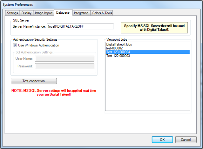
In the SQL Server section:
Server Name/Instance: This field is where you specify your SQL Server information.
In the Authentication/Security Settings section:
Authentication/Security Settings: These options allow you to either use Windows Authentication or enter your custom User ID and Password.
In the Viewpoint Jobs section:
Digital Takeoff Jobs: This box lists the Jobs in the selected database.
Test Connection: This option connects Digital Takeoff to the Server using the information you have provided.
The Integration tab contains the options you need to link Digital Takeoff Layers to the Takeoff Levels of each division. Use these options to link your Layers with the Levels, so that changes to the Layers will also be made to the Levels and vice versa.
NOTES:
You cannot use the same level integration for layers and sheets.
There is a maximum of 500 levels. If you exceed 500 levels by importing more than 500 sheets with integration turned on, the excess will not be linked.
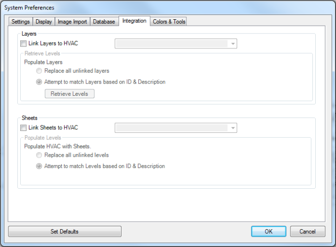
In the Layers section:
Add a check mark next to Link Layers and then select a Level Type in the field next to it to integrate Digital Takeoff Layers with the selected Takeoff Level Type. Once you have established your integration, all new jobs and estimates will automatically import the Takeoff Levels into your Layers. Changes to the Layers will update the Takeoff Levels (and vice versa). Also, changing the layer that annotations are assigned to will automatically update their Takeoff Level (and vice versa). Once you link layers on the Integration tab, new layers assigned to that division will automatically create matching levels.
Retrieve Levels:
Retrieve Levels allows you to both manually import Takeoff Levels into Digital Takeoff Layers, as well as establish how Takeoff Levels will be imported for new jobs and estimates. If there are layers linked to levels of a different type (than the type being imported), Estimating will break the links between those layers and the takeoff levels. There are two options:
Replace all unlinked layers: When the Takeoff Levels are imported, any existing unlinked layer belonging to the active Division (Electrical, Mechanical, or HVAC) will be replaced with newly created layers containing the Level IDs and Descriptions of the integrated Takeoff Level Type.
Attempt to match Layers based on ID & Description: If this option is selected, Estimating will attempt to match up the Takeoff Level IDs and Descriptions with existing Layers, and if a matching layer is found, link the two. If no match is found, a new layer will be created for the imported Layer.
Select Retrieve Levels. to start the import of Levels into Layers, according to the option you selected above.
In the Sheets section:
Add a check mark next to Link Sheets and then select a Level Type in the field next to it to integrate your sheets with the selected Takeoff Level Type. Once you have established your integration, all sheets you add to Digital Takeoff automatically import into the selected level type. Changes to the sheets will update the Takeoff Levels (and vice versa).
Populate Levels:
Populate Levels controls how Digital Takeoff Sheets are imported into the Takeoff Levels. There are two options:
Replace unlinked layers: When adding new Sheets to Digital Takeoff, no attempts will be made to match the Sheet name or ID to existing Levels in Takeoff. Any unlinked Level will be replaced.
Attempt to match Levels based on ID & Description: When adding new Sheets to Digital Takeoff, it will attempt to find an existing level with the same ID/Description as the newly added Sheet. If no match is found, the program will attempt to add a new level in an unused slot. If there are no unused slots, then the program will overwrite an unlinked Level.
To save your settings as your Database defaults, select Set Database Defaults.
To save your changes for the current session, select OK.
The options in this tab offer additional customizing for Digital Takeoff annotations.
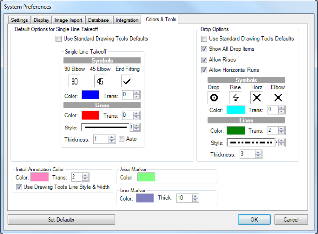
Default Options for Single Line Takeoff:
If you place a check mark in the Use Standard Drawing Tools Defaults check box, the preferences selected in the Sheet Setup for Single Line Takeoff and/or Drop Options will be used. Checking this box will override the SLT default colors, line styles, etc. and replace them with the main Digital Takeoff current settings in the Takeoff Tools panel.
The options in this tab allow you to change the Line Color, Transparency, Style, Thickness and Auto (to fill in the segment) for Single Line Takeoff, Drop and Marker Options.
See Drawing Tools for more information.
Drop Options:
In the Drop Options section:
Check Use Standard Drawing Tools Defaults to use the standard drawing tools in the main Digital Takeoff settings in the Takeoff Tools panel instead of defining a line style, color, thickness and transparency to use for all drops, rises, and horizontal runs.
Check Show All Drop Items to always display the drop lines and/or elbows by default. De-select this to hide these annotations by default and only show the appropriate Drop, Rise or Horizontal Run symbol.
Allow Rises controls the availability of the "finish" commands on the tool bars, menus and context menus in Digital Takeoff (ex. Finish with Rise).
Allow Horizontal Runs controls the availability of the of the add and finish Horizontal Run commands on the tool bars, menus and context menus in Digital Takeoff (ex. Add Horizontal Run).
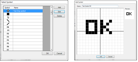
Symbols: Select the symbols you want to use for Drop, Rise and Elbow. Click in the field under Drop, Rise, Horz and/or Elbow (depending on the Drop Options selected) to open the Select Symbol dialog. Here, you can add, edit or delete symbols used on your drawing for these options.
To add a symbol, select Add. To edit a symbol, highlight the item and select Edit.
On the Add Symbol (or Edit Symbol) dialog, use the mouse to "draw" with the cursor to fill in blocks to create, or edit, your symbol. To draw pixels, hold the left mouse button down. To erase pixels, hold the right mouse button down. Hold either button down and drag the mouse to draw or erase multiple pixels.
Select OK to save. The updated symbol is added to the Select Symbol list.
Lines: Select the color, transparency, style and thickness to use for all drops, rises and horizontal runs. These options are not available if Use Standard Drawing Tools Defaults is selected.
Initial Annotation Color:
Choose the Initial Annotation Color and transparency (Trans.). This selection will be used for all annotations when they are initially drawn.
Use Drawing Tools Line Style & Width - check this to use the current Drawing Tools' Line Style & Width for line annotations. De-select this box if you do not want to use the current drawing’s settings.
Markers:
Select/edit the style and colors used for both the Area Marker and Line Marker tools.
To save your settings as your defaults, select Set Defaults.
To save your changes for the current session only, select OK.