The Fitting Standards contains a tree,.To makes edits,
select the ![]() , and select the next level in
the tree by using the
, and select the next level in
the tree by using the ![]() again,
as seen in Figure 1
again,
as seen in Figure 1
Figure 1
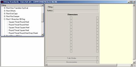
You can now select an item. As you select it, notice that the Dimensions (to the right of the tree in the grey area) become active.
To edit a dimension, you must move the mouse over the
![]() button next to the dimension that you want to edit.
For this example, select “Width 1.” Once the mouse is over the
button next to the dimension that you want to edit.
For this example, select “Width 1.” Once the mouse is over the ![]() button, left-click the
mouse (primary mouse button) on the
button, left-click the
mouse (primary mouse button) on the ![]() . Now you can
edit “Width 1” on the right, yellow portion of the screen, as seen in
Figure 2. You must left-click the mouse on the
. Now you can
edit “Width 1” on the right, yellow portion of the screen, as seen in
Figure 2. You must left-click the mouse on the ![]() to activate the edit screen for a dimension.
to activate the edit screen for a dimension.
Figure 2
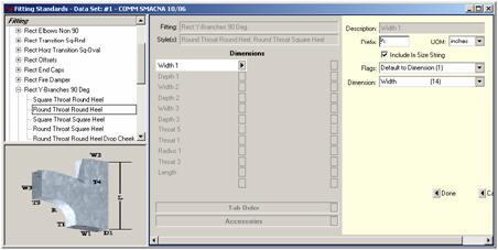
DESCRIPTION: This is the dimension that you are in. For this example, it is “Width 1.” It is not an editable value.
PREFIX: This serves as a quick identifier for the size it is attached to. It is useful when dealing with more than one size. When you assign a prefix to a size, the prefix will appear before the size in the item list. If no prefix is assigned, the first size will have no prefix, but all remaining sizes will default to a prefix of "x.”
UOM: This stands for "unit of measure,” and allows you to select how you want the size you are creating to be measured.
INCLUDE IN SIZING STRING: If this box is checked, that size will be included in the size description shown in Takeoff and Summary. For example, Straight Duct has a Width, Depth, Length, and Std. Length. Width & Depth have “Include in Size description” checked, so for a run of duct 24” wide, 12” high, 120’ long, with a Std. Length of 60”, the description shown in takeoff and summary would be 12” x 24”. If you checked Std. Length’s Include in Size Description (and gave it a prefix of Std:), it would display as 12” x 24” Std: 60”.
FLAGS: Depending on what the Flag is set to, the final editable field (in this case, “Dimension”) can be different. This last editable field will be one of the following: Dimension, Size, and Value. The final selection is Calculated Value. They are described below:
Dimension: When the Flag is set to “Default to Dimension (1)”, this field will display. The drop-down menu allows you to select the default value to the selected reserve dimension (located in Edit | Edit Dimensions).
Value: When the Flag is set to “Default to Value (2)”, this field will display. This is where you can manually enter a value.
Size: When the Flag is set to “Repeat Size (3)”, this field will display. Here, you can select the size you want from a drop-down menu. This repeats whatever size is selected (sizes are taken from the Dimensions in the middle, grey area).
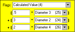
Calculated Value: This calculates the value depending on your selections, and goes from the left to right and down. Figure 3 shows that “Diameter 3” will be multiplied by “.5” (therefore cutting the value for “Diameter 3” in half). That value is then taken and added to “3” times “Diameter 2.” That will then be added to “2” times “Diameter 4.”
Figure 3
Note: If Flag is set to “Enter Always (0)”, there will be no field for “Dimension,” “Size”, “Value,” or “Calculated Value” edit fields.